People Carrier Drone.
An agricultural drone needs to perform the following functions:.
Most commercially available flight controllers such as a PX4 or a Pixhawk 2 or 4 or 6 etc can receive Mavlink commands for GPS coordinates via a local radio and fly to those coordinates.
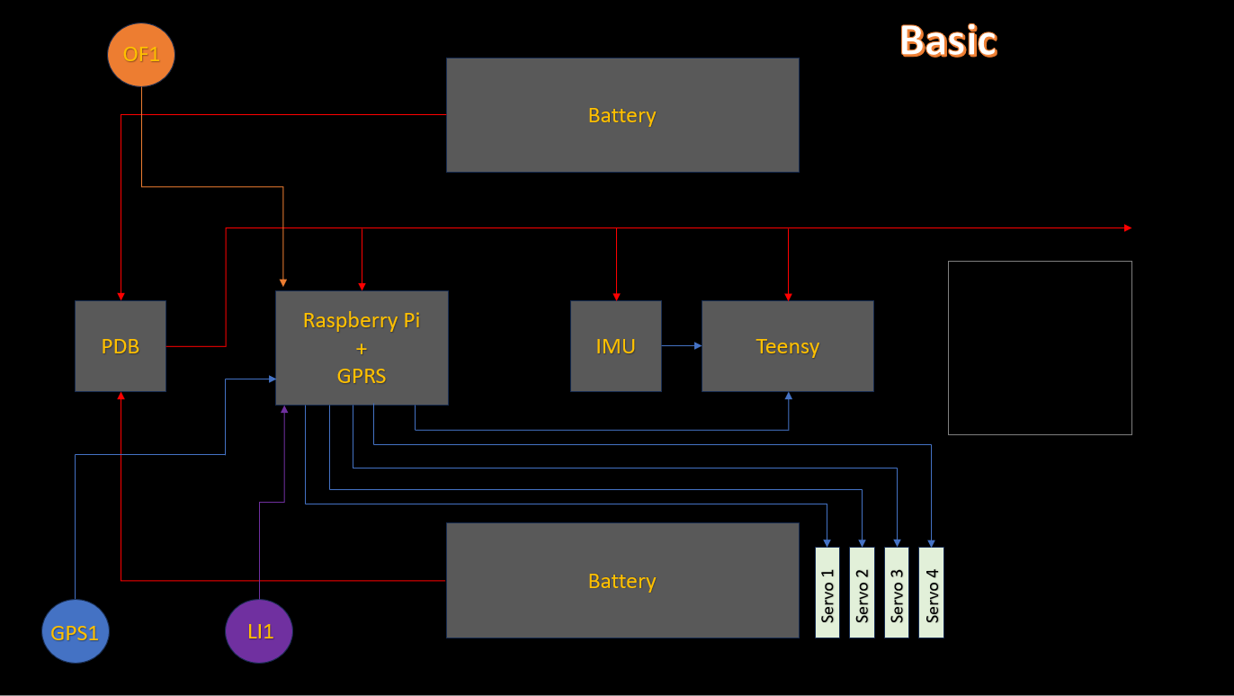
You can right click and open this layout in a new tab to inspect. It contains a teensy 4.1 microcontroller, a Raspberry Pi with cellular data, and a temperature stabilized IMU unit. OP1 is an optical flow unit and LI1 is a lidar unit.
The teensy code can be found here
This control is very organized and simple to understand as can be seen here in the main loop extract:
//========================================================================================================================//
//                                                       MAIN LOOP                                                        //
//========================================================================================================================//

void loop() {
  //Keep track of what time it is and how much time has elapsed since the last loop
  prev_time = current_time;
  current_time = micros();
  dt = (current_time - prev_time)/1000000.0;

  loopBlink(); //Indicate we are in main loop with short blink every 1.5 seconds

  //Print data at 100hz (uncomment one at a time for troubleshooting) - SELECT ONE:
  //printRadioData();     //Prints radio pwm values (expected: 1000 to 2000)
  //printDesiredState();  //Prints desired vehicle state commanded in either degrees or deg/sec (expected: +/- maxAXIS for roll, pitch, yaw; 0 to 1 for throttle)
  //printGyroData();      //Prints filtered gyro data direct from IMU (expected: ~ -250 to 250, 0 at rest)
  //printAccelData();     //Prints filtered accelerometer data direct from IMU (expected: ~ -2 to 2; x,y 0 when level, z 1 when level)
  //printMagData();       //Prints filtered magnetometer data direct from IMU (expected: ~ -300 to 300)
  //printRollPitchYaw();  //Prints roll, pitch, and yaw angles in degrees from Madgwick filter (expected: degrees, 0 when level)
  //printPIDoutput();     //Prints computed stabilized PID variables from controller and desired setpoint (expected: ~ -1 to 1)
  //printMotorCommands(); //Prints the values being written to the motors (expected: 120 to 250)
  //printServoCommands(); //Prints the values being written to the servos (expected: 0 to 180)
  //printLoopRate();      //Prints the time between loops in microseconds (expected: microseconds between loop iterations)

  // Get arming status
  armedStatus(); //Check if the throttle cut is off and throttle is low.

  //Get vehicle state
  getIMUdata(); //Pulls raw gyro, accelerometer, and magnetometer data from IMU and LP filters to remove noise
  Madgwick(GyroX, -GyroY, -GyroZ, -AccX, AccY, AccZ, MagY, -MagX, MagZ, dt); //Updates roll_IMU, pitch_IMU, and yaw_IMU angle estimates (degrees)

  //Compute desired state
  getDesState(); //Convert raw commands to normalized values based on saturated control limits

  //PID Controller - SELECT ONE:
  controlANGLE(); //Stabilize on angle setpoint
  //controlANGLE2(); //Stabilize on angle setpoint using cascaded method. Rate controller must be tuned well first!
  //controlRATE(); //Stabilize on rate setpoint

  //Actuator mixing and scaling to PWM values
  controlMixer(); //Mixes PID outputs to scaled actuator commands -- custom mixing assignments done here
  scaleCommands(); //Scales motor commands to 125 to 250 range (oneshot125 protocol) and servo PWM commands to 0 to 180 (for servo library)

  //Throttle cut check
  throttleCut(); //Directly sets motor commands to low based on state of ch5

  //Command actuators
  commandMotors(); //Sends command pulses to each motor pin using OneShot125 protocol
  servo1.write(s1_command_PWM); //Writes PWM value to servo object
  servo2.write(s2_command_PWM);
  servo3.write(s3_command_PWM);
  servo4.write(s4_command_PWM);
  servo5.write(s5_command_PWM);
  servo6.write(s6_command_PWM);
  servo7.write(s7_command_PWM);

  //Get vehicle commands for next loop iteration
  getCommands(); //Pulls current available radio commands
  failSafe(); //Prevent failures in event of bad receiver connection, defaults to failsafe values assigned in setup

  //Regulate loop rate
  loopRate(2000); //Do not exceed 2000Hz, all filter parameters tuned to 2000Hz by default
}
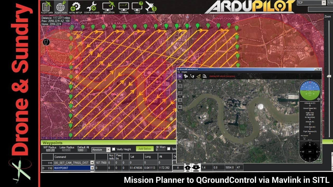
QGroundControl, a popular and free navigation program allows the drone to also cover areas automatically. And the Mavlink navigation protocol includes commands to activate servo motors which can control seed dispensors and sprayers..
Mission Planner, is another free navigation control program that is very similar. At i-Zone-3, we are currently writing our own software to take this a few levels forward.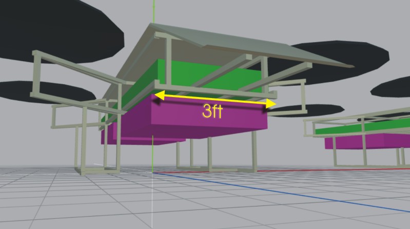
At the current time (April 2025), we have begun building an agricultural drone in Medellin Colombia. The design is in wings3d format here:
Wings3D Drone FileWe may use a Pixhawk 6 using Mavlink servo commands to activate a seed spreader and a pesticide spray - or we may do that via a Raspberry Pi and Teensy .
We also need to record band pass images of crops at various locations - so we are investigating both options
Will post video of progress here and on our blog..
This video is May 2025 - Medellin Colombia workshop. Joint welds will next need to be grinded down till smooth..
June 2025 - motors and controllers and props.
Thanks.
People Carrier Drone.
Police Drones.
Space Plane.
Celestial and Earth feature Navigation.
We currently have two facilities - one in Atlanta GA USA and one in Medellin Colombia South America.
Our Medellin facility allows us to prototype most things at lower cost than our Atlanta facility - especially building most test craft big or small.